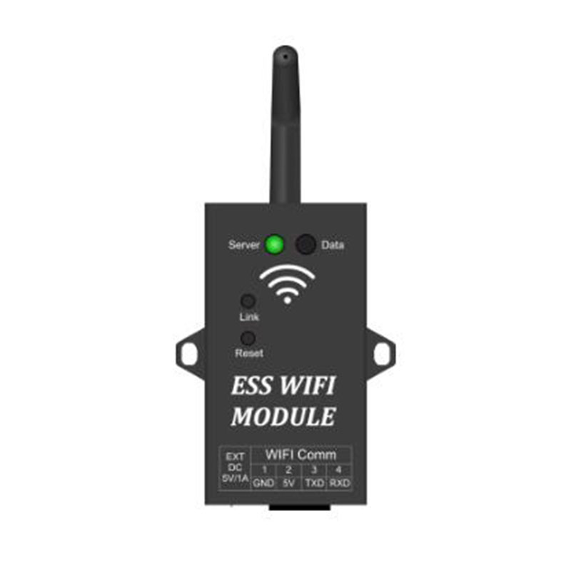
WiFi module connects the distribution network to the local network (wireless hot spot) through mobile app. If the distribution network connection is finished, WiFi module is automatically connected to the Cloud server. App connects the system to the server by adding devices (WiFi module MAC address). The system uploads the running data to the server through WiFi module every 10 minutes. The mobile app receives the data about the system on the server and show it on the interface. WIFI module picture and instruction
Server LED: Network status indicator
1S Flash: Network abnormal,Server connection
failure 0.3S Flash: Distribution network state
Light on: Network normal,Server connection success Data LED: Data is transmission, flash once every 10 minutes
Link button:Distribution network button ,Press and hold to enter the distribution network state Reset button:module restart button
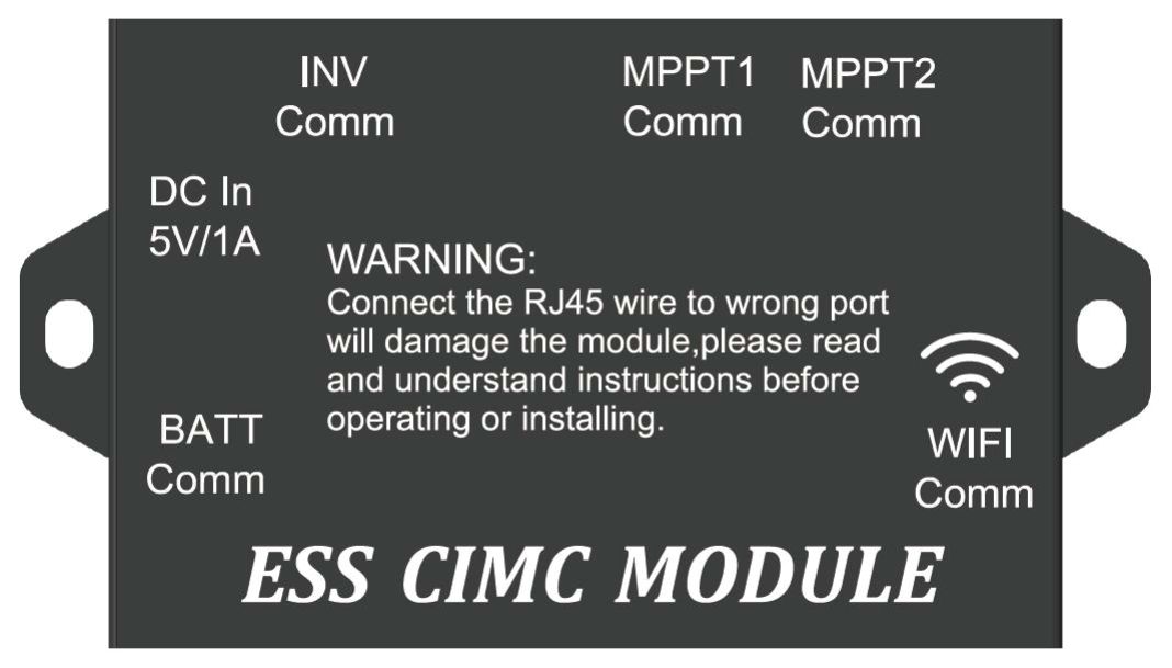
MPPT1&2 Comm:RJ45 blue 1.5M 8P network cable is adopted to connect with MPPT solar charger Remote Comm
INV Comm:RJ45 blue 1M 8P network cable is adopted to connect with inverter LCD Remote Port
BATT Comm:RJ11 blue 4M 8P network cable is adopted to connect with battery pack RJ45 Comm
WIFI Comm:RJ45 blue 10M 8P network cable is adpoted with WIFI module RJ45 Comm
DC In5V/1A:Backup 5VDC power interface
LCD module、Wiring and display instruction
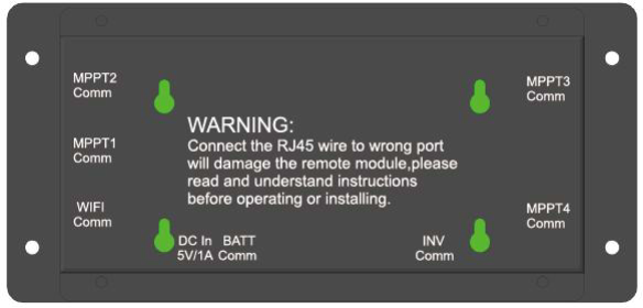
MPPT1&2 Comm:RJ45 blue 1.5M 8P network cable is adopted to connect with MPPT solar charger
Remote Comm
INV Comm:RJ45 blue 1M 8P network cable is adopted to connect with inverter LCD Remote Port
BATT Comm:RJ11 blue 4M 8P network cable is adopted to connect with battery pack RJ45 Comm
WIFI Comm:RJ45 blue 10M 8P network cable is adpoted with WIFI module RJ45 Comm
DC In5V/1A:Backup 5VDC power interface
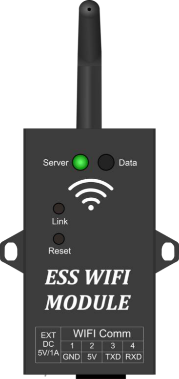
WiFi module connects the distribution network to the local network (wireless hot spot) through mobile app. If the distribution network connection is finished, WiFi module is automatically connected to the Cloud server. App connects the system to the server by adding devices (WiFi module MAC address). The system uploads the running data to the server through WiFi module every 10 minutes. The mobile app receives the data about the system on the server and show it on the interface. WIFI module picture and instruction
Server LED: Network status indicator
1S Flash: Network abnormal,Server connection
failure 0.3S Flash: Distribution network state
Light on: Network normal,Server connection success Data LED: Data is transmission, flash once every 10 minutes
Link button:Distribution network button ,Press and hold to enter the distribution network state Reset button:module restart button
MPPT1&2 Comm:RJ45 blue 1.5M 8P network cable is adopted to connect with MPPT solar charger Remote Comm
INV Comm:RJ45 blue 1M 8P network cable is adopted to connect with inverter LCD Remote Port
BATT Comm:RJ11 blue 4M 8P network cable is adopted to connect with battery pack RJ45 Comm
WIFI Comm:RJ45 blue 10M 8P network cable is adpoted with WIFI module RJ45 Comm
DC In5V/1A:Backup 5VDC power interface
LCD module、Wiring and display instruction
MPPT1&2 Comm:RJ45 blue 1.5M 8P network cable is adopted to connect with MPPT solar charger
Remote Comm
INV Comm:RJ45 blue 1M 8P network cable is adopted to connect with inverter LCD Remote Port
BATT Comm:RJ11 blue 4M 8P network cable is adopted to connect with battery pack RJ45 Comm
WIFI Comm:RJ45 blue 10M 8P network cable is adpoted with WIFI module RJ45 Comm
DC In5V/1A:Backup 5VDC power interface
Welcome to our website. If you have any requests or suggestions,please feel free to email us at [email protected] or use the following enquiry form. Please allow us to provide you with the best service.
Welcome to our website. If you have any requests or suggestions,please feel free to email us at [email protected] or use the following enquiry form. Please allow us to provide you with the best service.